The Engineering Change Processing
application allows the user to make modifications to a product structure
without immediately implementing those changes in the production process.
Modifications are stored in a separate file until the Post Engineering
Changes application is run. At that time, the user may specify which
changes are to be made to the Product Structure File.
Before they are posted, engineering changes may be
changed, deleted, and/or printed on the Engineering Change Edit List. After
posting, engineering changes may be printed using the Engineering Change
History Report application.
When making an engineering change, the user will
be prompted to enter the parent item number of the product structure to be
modified. This is followed by a brief description of what the change involves
or any other relevant information that the user wants to be printed on the edit
list and Engineering Change History report. The user will then be
prompted to enter a sequence number. Components will display and print
according to this sequence number. If the sequence number entered already
exists in the product structure, the user may choose to either change or delete
it. If the sequence number is new, it must be added to the product structure
before it can be modified. The user may then enter specific information
related to the component item. For more information on product structures,
consult the Product Structure File Maintenance application section of
this manual.
Select Engineering Change
Processing from the pull down BOMP Processing window. The following
screen will then be displayed:
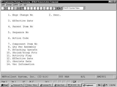
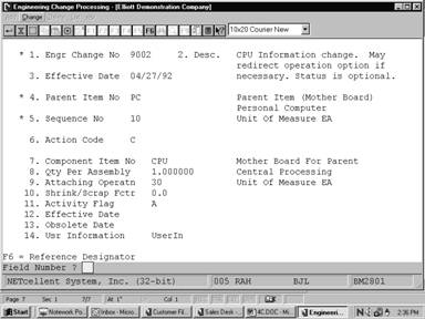
Engineering Change Processing Entry Screen
The following options are
available:
* Select the
desired mode from the Engineering Change Processing menu bar.
* Enter the
data requested on the screen.
To return to the menu bar,
press the ESC key. To leave this application, press X for EXIT
when positioned at the menu bar.
Entry Field Descriptions
|
Name
|
Type
and Description
|
|
1. Engr Change No
|
6 numeric digits.
Enter the engineering change
number. In add mode, press the F1 key to bring up the next
engineering change number on file.
|
|
2. Desc.
|
3 lines of 30 alphanumeric
characters each.
Enter a description of the engineering change. This
description will be printed on the Engineering Change Edit List and the
Engineering Change History Report.
A blank description is not
allowed.
|
|
3. Effective Date
|
A date in the standard date
format.
Enter the date on which the engineering change should
become effective.
Note:
Engineering changes do not affect product structures until posted in the Post
Engineering Changes application. Default is the current date.
|
|
4. Parent Item No
|
15 alphanumeric characters.
Enter the parent item number
whose component will be affected by the engineering change. In add mode,
press the F7 key to search by item number or press the F8 key
to search by item description.
|
|
5. Sequence No
|
3 numeric digits.
Enter the sequence number, which will be used with the
parent item number in this product structure record. The sequence number may
not be zero and a parent may not have records with the same sequence number.
In add mode, press the F1
key to search for the next available sequence number in the product
structure. Press the F7 key to search existing components. In change
mode, press the F1 key to search for sequence numbers already on file
for this engineering change. Press the F7 key to search for existing
components, or the F8 key to search for engineering changes.
|
|
6. Action Code
|
1 alphabetic character.
Enter the action code representing what is to be done
to this particular sequence number. The user may enter one of three values:
A = Add
C = Change
D = Delete
If the sequence number
already exists in the product structure, it may only be changed or deleted.
If the sequence number is new to the product structure, it may only be added.
|
|
7. Component Item No
|
15 alphanumeric characters.
Enter the item number of the component to be linked to
the sequence number. If the sequence number already exists in the product
structure, the item number and description will display automatically. The
user may change the item or leave it alone.
Press the F7 key to
search for an item by number, or press the F8 key to search for an
item by description.
|
|
8. Qty Per Assembly
|
10 numeric digits with 6
decimal places and an optional minus sign (9999.999999-).
Enter the quantity per
assembly for this product structure record. This is the number of component
items needed to make one parent. Entry is not required.
|
|
9. Attaching Operatn
|
4 numeric digits.
Enter the number of the
operation in this parent's routing where this component is to be used or
attached.
|
|
10. Shrink/Scrap Fctr
|
4 numeric digits including 1
decimal place (999.9).
Enter the percentage of the
component which is anticipated to be lost due to scrap, shrinkage, etc.
|
|
11. Activity Flag
|
1 alphanumeric character.
Enter the desired value for the component's activity
flag. This flag can have one of three values:
A = Active
F = Forecasted
O = Obsolete
An active item is one currently in use or being sold to
customers.
A forecasted item is one, which is forecasted to be
active in the near future.
An obsolete item is one
which is no longer a standard part, though there may still be a supply of the
item on hand which can be sold or used in other manufacturing processes.
|
|
12. Effective Date
|
A date in the standard date
format.
Enter the effectivity date
for this component. If the item has no effectivity date, this field may be
left blank. If the item is forecasted, this is the date the item should
become active.
|
|
13. Obsolete Date
|
A date in the standard date
format.
Enter the obsolete date for
this component. If the item has no obsolete date, this field may be left
blank. If the item is active, this is the date the item should become
obsolete.
|
|
14. Usr Information
|
6 alphanumeric characters.
The name for this field may be defined by the user in
the BOMP Setup application. The field can be used for any purpose the
user desires.
This field is not displayed
if the user-defined field in BOMP Setup is blank.
|
|
F6 = Reference Designator
|
3 lines of 60 alphanumeric
characters each.
This field can be used to
show a routing of a component item. It will be printed on work orders and
may be printed on several reports.
|
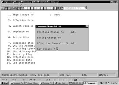
Engineering Change Edit List
|
Name
|
Type
and Description
|
|
Starting Change No
|
6 numeric digits.
Enter the starting
engineering change number for the range of engineering changes to be
printed. Defaults to All.
|
|
Ending Change No
|
6 numeric digits.
Enter the ending engineer
change number for the range of engineering changes to be printed. Defaults
to the starting engineering change number.
|
|
Effective Date Cutoff
|
A date in the standard date
format.
Enter the cutoff date for
the range of engineering changes to be printed. Only engineering changes
with effective dates on or before the date entered will be printed. Defaults
to All.
|
Screens
Engineering Change
Processing
Sequence Number Selection
E N G I N E E R I N G C H A N G E E D I T L I S T
Ranges:
All Changes
All Dates Printed
Change
No Change Description Parent Item Parent
Description Effective Date
9002 CPU Information change. May PC Parent Item (Mother
Board) 04/27/92
redirect operation option if Personal Computer
necessary. Status is optional.
Seq
Action Component Item Qty Per Um Component Description Llc Attch
Scrap Act Stk Ctl P/M Eff Date
10
C CPU 1.000000 EA Mother Board For Parent 1 30
.0 A Y Y M 00/00/00
Central Processing
CPU 386 operation position 30. Maintain inspection status
for sub‑assembly CPU. Operation position is portable as
needed. Inspection operation may need additional queue.
1
Changes Printed
